A synchronized light show in Alpharetta Georgia. Over 65,000 Lights.
Putting it Together
My hope is that this page won't scare off anyone who is thinking about doing a show. I tell people, "There are a lot of moving parts but it's like a jigsaw puzzle, if you can see the picture the parts make more sense." The intent of this page is to use the layout of our 2021 Christmas show as the "picture on the puzzle box" and show how all the parts make sense when they come together.

The Brain | The Show Computer
-
While there are many ways to run an animated light show, we run ours from a Windows Laptop located in the garage. We use Light-O-Rama software installed on the laptop to manage the following tasks:
-
Define the Show(s) – This includes identifying the sequences (songs) and the order in which they will be played.
-
Schedule the Show(s) – This allows us to specify the specific show to run and the times it should start and end. Because we had two 16 minutes shows that we ran on alternating nights, the scheduler handled which show to run each night.
-
Run the Show – The show player sends the lighting control commands to all the controllers as well as playing the sound/music.
The FM Transmitter
Without the FM Transmitter everyone would have to stand in the garage or we would have to provide speakers in the yard (which would not please our neighbors). Instead, we plugged an FM Transmitter into the headphones jack on the laptop and it transmitted the sound/music over the radio waves on frequency FM 89.7.
Controller Stations
Because light controllers need to be located near (typically within 25 feet) the lights they control, it is necessary to position them throughout the yard. We solve this problem by positioning what we call “Controller Stations” throughout the yard. In addition to supporting one or more controllers a station will also have a source of A/C power and an Ethernet Switch. For our show we had 8 stations with 4 ethernet switches and 29 waterproof enclosures housing 31 controllers.
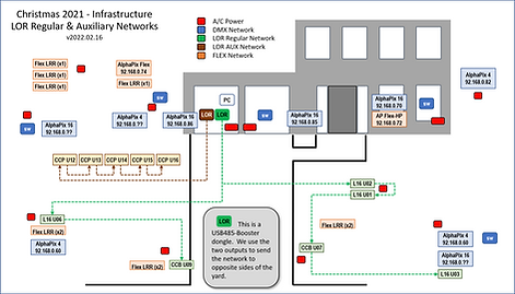
The diagram below shows the placement of our controllers and stations. For more information check out our Controllers page.

Light Controllers
We used the following controllers in our show:
5 - AlphaPix 16
4 - AlphaPix 4
1 - AlphaPix Flex Evolution CPU with 2 x 4 Port Long Range Expansion boards
1 - AlphaPix Hinkspix CPU with 16 Channel SPI board and 1 x 4 Port Long Range Expansion board
10 – AlphaPix Flex 4 Port Long Range Receiver (Regular)
3 - Light-O-Rama 16 Channel A/C (L16)
2 - Light-O-Rama Cosmic Color Bulb (CCB)
5 - Light-O-Rama Cosmic Color Pixel (CCP)
A/C Power
Most of our lights are powered by 12-volt DC power, but the controllers that control them still need A/C power to operate. That means A/C power needs to be distributed throughout the yard. The diagram below shows our power distribution points and routes using red boxes and lines. We distribute all of the A/C power from two circuits in the garage to power strips mounted on controller stations throughout the yard.
The diagram below shows the distribution of A/C power for our show.

Controlling the Lights
Now that we've got the stations set up, the controllers distributed and connected to A/C power it's time to connect them to the computer so they can receive signals to control the lights. For more information check out our Network page.
Light-O-Rama Networks
Since we use the Light-O-Rama (LOR) software, we use their proprietary network to communicate with our LOR controllers. We use two two dongles plugged into USB ports on the show computer to originate the LOR networks. One dongle addresses the LOR “Regular” network and the other dongle addresses the “AUX” network. These dongles are connected to the LOR controllers via CAT-5 cables. LOR supports daisy-chaining from controller to controller so no switches are needed. The dongles are shown in the diagram below as brown (AUX network) and green (Regular network) boxes (with “LOR” labels) and corresponding-colored lines.
The diagram below shows the components of the LOR networks.
DMX/Ethernet Networks
The DMX/E1.31 controllers get their signal from the ethernet port on the show computer. DMX controllers require a dedicated connection to the ethernet network so there is no daisy-chaining. Some of the newer controllers handle this by building in network switches into their controller (to allow simulating daisy-chaining). To address the issue, we distribute Network Switches throughout the yard to manage all of the ethernet connections/traffic with shorter/less cables. We have one 5 port switch in the garage from which all ethernet networks start. We have 3 additional switches mounted on controller stations at key points throughout the yard.
The diagram below shows the DMX Network. The switches are shown as blue boxes with “SW” labels.

Holiday Coro FLEX Network
Many of our newer DMX controllers use a distributed type of network that allows the "controller" to be in a main box to distribute the light control commands to other "receiver" boxes throughout the yard. The communication between the main box and the receiver boxes are handled through a proprietary (not ethernet) network.
The diagram below shows the HC FLEX network.

Keeping the Cables Straight
Connectivity between the show computer and all of the controllers is handled using CAT-5 cables. Because CAT-5 cables are used for all of the different network types, it is very important to verify the source and target of both ends of a cable. Pugging the target end of a cable that starts in an LOR controller into a DMX controller will likely fry the DMX controller because LOR includes power on their data line.
Disclaimer | Information on this page is purely our opinion, learned from our years of experience doing our show. We may have acquired our knowledge using other sites but it is not our intent to suggest that our conclusions are shared by the authors of those sites. This page mentions retail stores as a reference to where we purchased items. We are not affiliated with those stores and use of their name, and product images, has not been authorized by them.